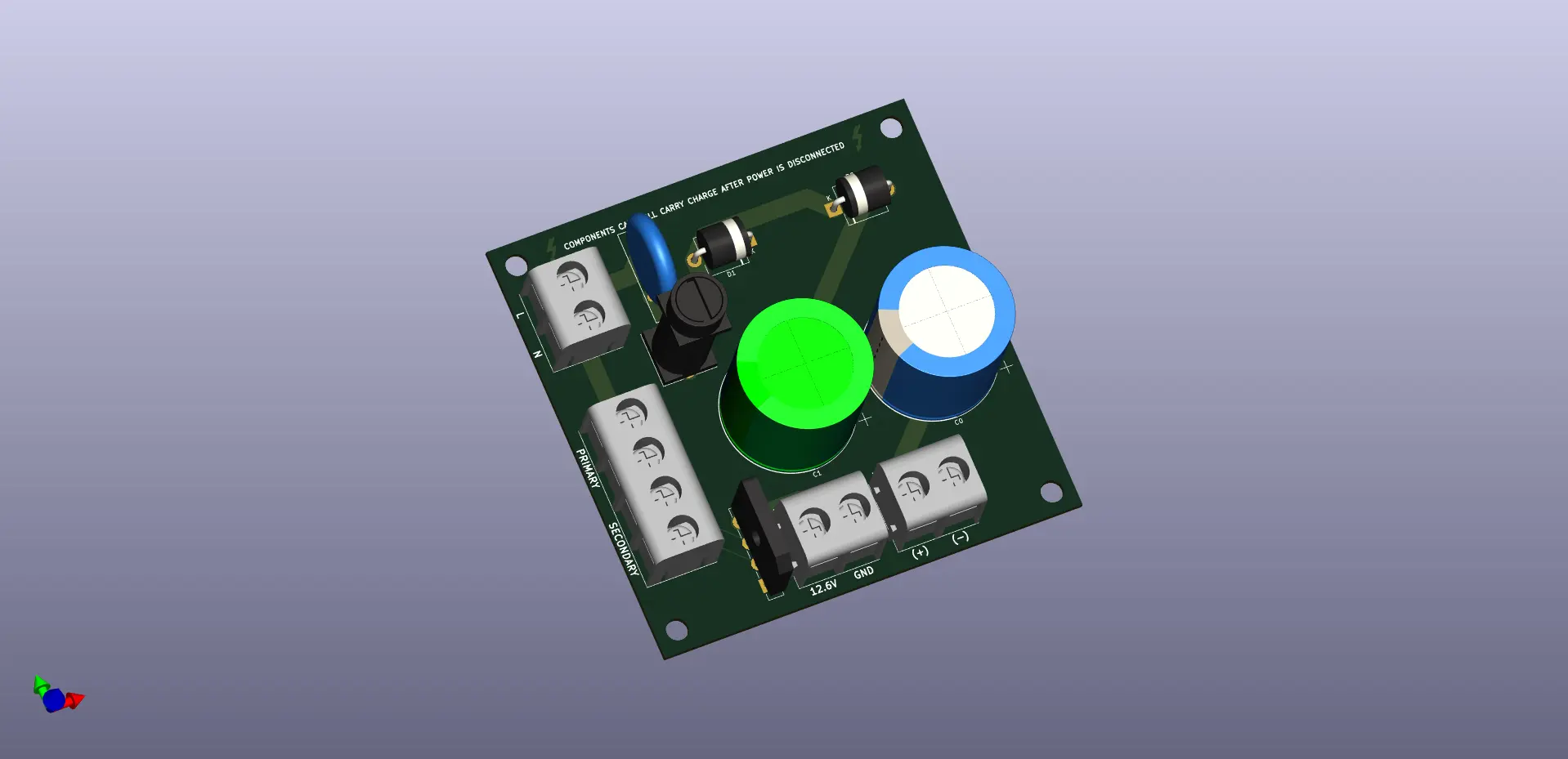
The power supply for my coil needs to fill two roles. It must generate a 340V DC voltage (max 10A) and a minimum 12V DC voltage (max 1A). I started my design from Plasma Prince's design.
I initially used a KBU1010 bridge rectifier in my design, however, I was concerned about the pin clearances with the voltages in use. I opted to use discrete 10A10 diodes. These rectify the flow before going through a pair of chunky electrolytic capacitors to double the voltage. I retained the NTC in the design to deal with inrush current. For the low voltage side, a step down transformer brings 120VAC down to 12.6VAC. I know the downstream driver board will likely use a 7812 regulator, so the extra 0.6V ensures it doesn't drop out. A GBP310 bridge rectifier is used to convert AC to DC. Since the power socket will have a 10A fuse, I need a separate fuse for the low voltage side

To save on board space, the transformer will be hooked up via a barrier block. The fuse holder chosen mounts the fuse vertically
